Data from Peripherals have to reach Memory so that the CPU can use it. Similarly, the processed output has to reach peripherals like printer, internet devices, DISK, etc.
Thus, I/O data transfer is about how the three subsystems i.e. CPU, Memory and I/O Controller, are involved in achieving the data exchange with peripherals. The word Data Exchange means successful Data in/Data Out with necessary handshake and coordination.
Data Exchange with a peripheral involves few steps and not straight forward as devices are mostly electromechanical and/or operate at a different speed than CPU and Memory.
I/O Controller's role is to ensure seamless data exchange by ensuring the following (Please refer to diagram 20.2)
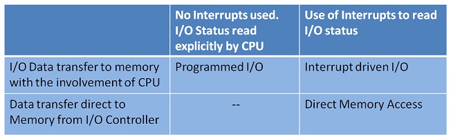
CPU can be used very efficiently in Multitasking. Ideally, the involvement CPU in I/O data transfer is expected to be minimal. There are three possibilities for I/O Data exchange.
A program controls the I/O Operation; hence CPU is fully involved. CPU Monitors the status of the device and the I/O data transfer. This keeps the CPU hooked until the I/O operation is completed for the desired number of bytes. In the case of READ from I/O device, the final destination for Data is Memory. CPU writes the data collected from the device into Memory. It happens vice versa in the case of WRITE onto the device.
Programmed I/O is used for tiny data transfer i.e. few bytes. Before an actual Data transfer to a device, selecting, readying the device and verifying the status are to be done. Ex: Selecting the Printer and initialization before printing. This is shown by the decision box loop in figure 20.2.
In the diagram, at each step, the direction of information flow between the subsystems is marked to reinforce your understanding.
The CPU loop during status check is eliminated in the Interrupt Driven I/O Operation.
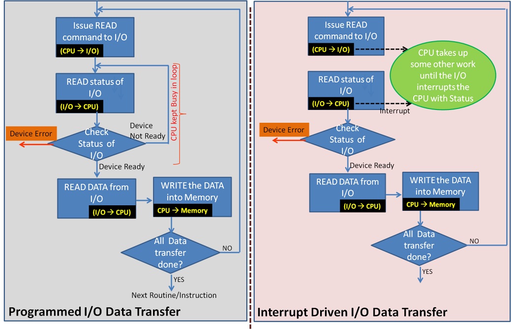
The steps involved in I/O data transfer are the same but for a change in freeing the CPU until the device is ready for data transfer. Refer to figure 20.2.
Most of the devices are electromechanical and have high latency. The period for which the CPU is freed is proportional to this. Hence the benefit achieved is reasonable. The interrupt is asynchronous. The I/O controller waits until the interrupt is serviced by CPU. Thus, what we have achieved is the I/O controller is made to wait instead of the CPU. CPU time is more precious. Details of Interrupt servicing will be dealt with in the next chapter.
Interrupt service routine is also a complex and costly matter involving OS. This method is also feasible for a small quantum of data transfer. Direct Memory access can resolve the CPU availability in a hardware environment.
Interrupt servicing of the device is still accomplished using the software. This may not be fast enough for a large chunk of data transfer from DISK. Recall that the Virtual memory implementation is supported by Disk. This involves large data exchange to memory. The software routine is replaced with a specialized hardware processor, called the Direct Memory Access Controller (DMAC). DMA technique facilitates I/O data transfer between Main Memory and devices connected to DMAC, Fast data rate devices are connected to DMAC.
As seen in figure 20.3,
Note that the CPU as a boss gives the work and informed of Job done but not involved for doing the job. It is independently taken care of by DMAC.
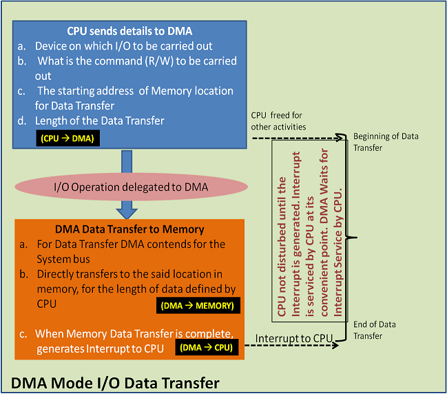
The DMA method improvises the interrupt method with optimal efficiency as the data is not routed via CPU. Thus DMA unburdens CPU. The details of DMAC and operations are dealt with in the next chapter.